Every brushless motor contains a set of windings that is essential to its operation. These insulated copper conductors are arranged around the stator and energized in sequence by the electronic speed control.
As the ESC switches current through the motor phases, the windings create a rotating magnetic field. This field interacts with the permanent magnets in the rotor, producing torque and causing the motor shaft or outer can to rotate.
The number of winding turns, wire arrangement, stator design and phase connection all influence motor Kv, resistance, inductance, current and operating characteristics.
What Is a Brushless Motor Winding?
A brushless motor normally uses three electrical phases. Each phase consists of copper wire arranged around part of the stator. The ESC energizes these phases in a timed sequence based on rotor position, speed and throttle demand.
The copper wire is coated with a thin electrical insulation, commonly called magnet-wire enamel. This allows adjacent strands and turns to touch physically without creating an electrical short circuit.
The winding design affects several important motor parameters:
- Motor Kv
- Torque produced per amp
- Winding resistance
- Inductance
- Maximum practical current
- Motor efficiency
- Heat generation
- ESC timing and control behaviour
Number of Turns in a Brushless Motor
A winding turn is one complete loop of a conductor around the applicable stator tooth or winding path. A motor described as having more turns generally has more loops of conductor in each phase.
Some performance motors are identified by their turn count, such as 4.5-turn, 6.5-turn or 13.5-turn motors. However, turn count alone does not provide enough information to compare motors from different manufacturers or motor families.
Stator dimensions, magnetic design, wire size, number of parallel strands, termination type and manufacturing quality also affect the final motor characteristics.
How Turn Count Affects Motor Kv
When the magnetic design and other motor dimensions remain unchanged, increasing the number of winding turns generally decreases motor Kv. Decreasing the number of turns generally increases Kv.
| Winding Change | General Result |
|---|---|
| More winding turns | Lower Kv, higher torque per amp, higher winding resistance and usually higher inductance |
| Fewer winding turns | Higher Kv, lower torque per amp, lower winding resistance and usually lower inductance |
This does not mean that a lower-Kv motor automatically produces more total torque or power. It means the motor produces more torque for each amp flowing through the winding when the motor constants are compared consistently.
The motor’s actual torque and power capability still depend on:
- Motor size
- Copper fill
- Winding resistance
- Magnet strength
- Stator construction
- Cooling
- Allowable winding temperature
- Maximum safe RPM
Higher Voltage and Lower Kv
A lower-Kv motor can often be paired with a higher battery voltage while maintaining a similar unloaded RPM. This can allow the same electrical input power to be delivered using less battery current.
For example, two systems may both operate near the same input power:
- 10 volts × 100 amps = 1,000 watts
- 20 volts × 50 amps = 1,000 watts
The higher-voltage system does not automatically run more efficiently, but reducing current can lower losses in batteries, connectors and wiring when those components remain otherwise comparable.
Should You Select a Motor by Turn Count?
Turn count is useful when comparing different winds from the same motor family. It is less useful when comparing unrelated motors.
For most RC applications, motor Kv is the more practical starting specification. Kv allows you to estimate unloaded RPM from battery voltage:
Approximate unloaded RPM = Motor Kv × Applied voltage
The actual loaded RPM will be lower because of motor resistance, current, timing, ESC operation and mechanical load.
Motor selection should also consider physical size, winding resistance, no-load current, voltage limit, current limit, cooling and the propeller, fan, gear ratio or driveline being used.
Learn How to Measure Brushless Motor Kv
One Turn Can Use Several Wire Strands
A motor described as a one-turn or 2.5-turn motor may appear to contain many more conductors. This is because one winding turn does not necessarily consist of one large wire.
Manufacturers can wind several smaller strands in parallel and treat the group as one conductor. The complete bundle travels around the stator together to form the specified turn.

Why Use Multiple Parallel Strands?
Several smaller strands can be easier to form around the stator than one large, stiff conductor. They may also fit into the available winding space more effectively.
The manufacturer’s goal is to place as much useful copper as practical into the available winding area while maintaining:
- Electrical insulation
- Consistent winding geometry
- Adequate cooling
- Mechanical support
- Manufacturing repeatability
A higher copper fill can help reduce winding resistance, but only when the winding is properly arranged and cooled.

Brushless Motor Winding Resistance
Every motor winding has electrical resistance. This value is commonly identified as Rm in motor specifications.
Current flowing through the resistance produces copper loss:
Copper loss = Current² × Winding resistance
Because current is squared, a relatively small increase in current can create a much larger increase in winding heat.
A higher-Kv winding commonly uses fewer turns of heavier conductor and has lower resistance. A lower-Kv winding commonly uses more turns and has higher resistance. The exact values depend on the complete winding design.
Learn About Measuring Brushless Motor Winding Resistance
Slotted and Slotless Brushless Motors
Brushless motors can use either slotted or slotless stator construction. Both designs can provide excellent performance, but they achieve it differently.
Slotted Brushless Motor Construction
A slotted motor contains laminated steel stator teeth. The windings are placed inside slots between these teeth.

The iron teeth guide and concentrate magnetic flux through the stator. This can provide high torque density and a mechanically robust winding structure.
Common Advantages of Slotted Motors
- High torque density
- Strong magnetic coupling between stator and rotor
- Windings supported by the stator structure
- Well-established manufacturing methods
- Wide selection of sizes, Kv values and power levels
One possible disadvantage is cogging torque. Cogging occurs because the permanent magnets tend to align with particular positions of the iron stator teeth.
Modern motor designs can reduce cogging through pole-and-slot selection, skewing, magnet shaping and controller strategy, but it may still be noticeable when the motor is rotated by hand.
Slotless Brushless Motor Construction
A slotless motor does not place the windings inside iron stator slots. Instead, the windings form a self-supporting or resin-supported structure in the motor’s air gap.
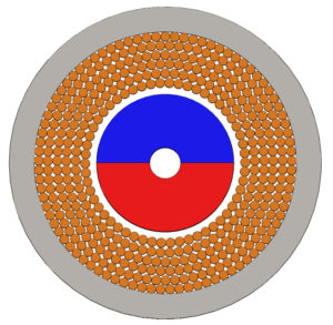
Common Advantages of Slotless Motors
- Very low or effectively eliminated cogging torque
- Smooth shaft rotation
- Reduced iron-related losses in the toothed portion of the stator
- Potential for high-speed operation
- Low torque ripple when combined with suitable motor control
Slotless construction does not automatically guarantee perfect sensorless low-speed starting. Sensorless ESCs still rely on rotor-position information inferred from the motor, which becomes more difficult at zero or very low speed.
Slotless motors can also have low inductance, which may place additional demands on the ESC and switching strategy. The motor and controller must be matched correctly.
Wye and Delta Motor Windings
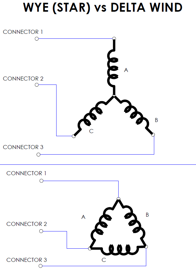
The three motor phases can be connected using two common termination arrangements: Wye, also called Star, and Delta.
Wye or Star Connection
In a Wye-connected motor, one end of each phase winding is connected to a shared centre point. The other end of each phase becomes one of the three motor leads.
Delta Connection
In a Delta-connected motor, the three phase windings are connected end-to-end in a closed triangular arrangement. Each motor lead connects to a junction between two phases.
Kv Difference Between Wye and Delta
If the same three phase windings could be reconnected without changing their turns or conductor arrangement, the Delta configuration would theoretically produce a line-to-line Kv approximately equal to the Wye Kv multiplied by the square root of three:
Delta Kv ≈ Wye Kv × 1.732
For example, a winding producing approximately 1,000 Kv in Wye would theoretically produce approximately 1,732 Kv when reconnected in Delta.
The measured terminal resistance and inductance would also change. However, it is not correct to assume that the motor will always draw exactly 1.732 times more battery current in actual use.
Actual current depends on:
- Battery voltage
- Motor speed
- Propeller, fan or drivetrain load
- ESC timing
- Winding resistance and inductance
- Motor back-EMF
- Cooling
A Delta-connected version of an otherwise similar motor is often described as a “hotter” wind because its terminal Kv is higher. For motor selection, use the manufacturer’s measured Kv, resistance and operating limits rather than attempting to select the motor from its termination type alone.
Winding Type and ESC Timing
Advancing ESC timing can increase motor RPM and may change efficiency, no-load current and operating temperature. The result depends on motor construction, winding design, load and ESC control method.
Very high-Kv, low-inductance motors can be particularly sensitive to inappropriate timing. Excessive timing may increase current and motor temperature without producing a worthwhile performance gain.
Use the motor manufacturer’s recommended timing whenever it is available. When no recommendation is provided, begin with a conservative timing setting and check current, RPM and temperature before making additional changes.
In my own high-performance inrunner testing, I have sometimes found Wye-connected winds easier to tune across timing changes. That is a personal observation rather than a rule that applies to every motor or ESC. Well-designed Delta motors can also provide excellent performance.
Can Brushless Motor Wires Be Shortened?
Some motors have flexible lead wires connected to the winding inside the motor. Other motors bring the enamel-coated winding conductors directly outside the motor case.
Do not cut or shorten the motor leads unless the manufacturer permits it and you understand how the leads are constructed.
Cutting a direct winding lead may:
- Remove a required termination point
- Expose enamel-coated wire that cannot be soldered normally
- Separate parallel strands
- Damage the winding insulation
- Make the motor difficult or impossible to reconnect
When flexible silicone wires have clearly been added as external leads, shortening may be possible, but the motor manufacturer’s instructions should still be followed.
Which Motor Winding Is Best?
There is no single winding type that is best for every application. The correct motor depends on the complete RC power system.
Important selection factors include:
- Required motor Kv
- Battery voltage
- Expected current
- Propeller, fan or gearing load
- Motor dimensions and weight
- Winding resistance
- No-load current
- Cooling
- Maximum safe RPM
I generally select the required Kv and motor size first rather than choosing a motor simply because it is Wye, Delta, slotted or slotless.
The termination and stator design help explain how the motor behaves, but the measured specifications determine whether it is suitable for the application.
Related Brushless Motor Resources
- Brushless Motor Efficiency Guide
- How to Measure Motor Kv
- Measuring Motor Winding Resistance
- Understanding Motor No-Load Current
- Comparing Similar Motors With Different Kv Values
Conclusion
Brushless motor windings determine much of how a motor responds to voltage, current and load. More turns generally produce a lower Kv and greater torque per amp, while fewer turns generally produce a higher Kv and lower winding resistance.
Multiple strands can be used together to form each turn, allowing manufacturers to improve winding construction and copper fill. Slotted and slotless stators provide different compromises in torque density, cogging, losses and control behaviour.
Wye and Delta describe how the three motor phases are connected, but neither connection is automatically better for every application. Select the motor using its measured Kv, resistance, current capability, thermal limits and suitability for the complete RC power system.
Pingback: Three Misconceptions in RC - Brushless Motors & more -
Pingback: Are We Incorrectly using Kv for an RC Brushless Motor? - RCexplained